
DN Specifications Interpretations
E. Runners
INTERPRETATIONS OF THE OFFICIAL SPECIFICATIONS BY THE TECHNICAL COMMITTEE
Effective May 31, 2020
E. Runners
1974: A slot may be machined on the top of allowed ``T’’ sections to facilitate mounting to wood body.
10/17/83: It is permissible to reinforce wood runner bodies (of regulated thickness) with materials like carbons, aluminum, tin, and similar materials. No kevlar.
11/23/87: Specifications for the thickness of ``T’’ sections and for insert steel are not the same.
11/23/87: Internal reinforcement of the wooden runner body: The use of threaded rod or bolts to attach ``T’’ iron to the wooden body with the rod extending up to the top of the wood body is a well accepted method of constructing these runners. The wood body of insert runners must meet all the requirements of Section E of the Specifications.
3/18/89: Specification E.2.h. establishes the maximum thickness of the steel plate in insert runners at .270 inches. Therefore, the absolute maximum thickness is .270’’ and plate in the thickness range .271’’ through .279” is not allowed.
11/14/89: Wood or metal stiffeners may be added to insert runners (as in E.1.e . for plate runners) as long as the minimum wood body meets the dimensions in E.2.a. and the stiffener is outside the wood body. No wood or metal stiffener may come between the insert plate and the slot on the wood body. No metal stiffening is allowed inside the main wood body.
7/1/92: The specifications do not prohibit the changing of the runner stiffening elements during a regatta. However, when the stiffening element is changed, the runner is then counted as a new runner in total count of the nine runners allowed.
7/1/92: Commercially available T, angle, or plate is manufactured in a quantity to be sold to people who want to purchase it. If the T, angle or plate is made only in small quantities for a few people, it is a special fabrication and not allowed to be used. A modification of a commercially available T, angle, or plate by procedures such as surface grinding, milling, bending or flattening is allowed.
11/30/98: The body of a wood body runner must be constructed of wood and adhesive only. No internal reinforcement is allowed except for threaded rod, or bolts, or screws used to attach the steel to the body. The wood body must meet all specifications before the application of external reinforcement. Reinforcement between the blade and body (inside the slot) on insert runners is considered to be outside the wood body and is allowed.
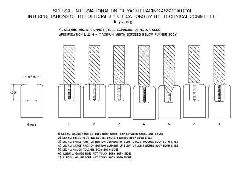
2/10/07: Measuring spec. E.2.h: A simple measuring gauge may be used to measure the amount of exposed steel on insert runners. The gauge should have a slot width at the minimum wood body thickness (7/8” or 22.3 mm) and depth at the maximum allowed exposure (1-1/2” or 38.12 mm) . This gauge is used as shown on the next page (130) to measure exposed steel. The top of the gauge should touch the bottom of the runner body. The edge of the steel may touch the bottom of the slot, or there may be a gap between the edge of the steel and the gauge. If the edge of the steel is touching the bottom of the slot and both top edges do not touch the bottom of the runner body, then the exposed steel is greater than the maximum allowed.
Notes:
- Because it is impossible to determine the thickness of any reinforcement on the bottom of the runner body, the gauge should be used to measure to the outside of the reinforcement.
- This gauge should not be used on the front 6” (152 mm) of the runner (This gauge should not be used on the front 6” (152 mm) of the runner (where Spec. E.2.i. allows the body thickness to be reduced below 7/8”)
- Allowance should be made for small imperfections (porosity, damage, etc.) on the bottom surface of the runner body
1/15/2010: The reinforcement bar or stiffening element that is associated with the “Kent” style chock is part of the runner and must meet all requirements of a runner stiffener, Reference Specifications E.1.e; E.1.f; E.4; Interpretations B. Runner Plank, 1/15/2010; E. Runners, 11/14/89, 7/1/92, 1/15/2010, and I. Fittings, 1/15/2010
1/15/2010: All runner stiffening elements are considered part of the runner and are included in the runner weight. Reference Specification E.6.
1/15/2010: The specification making optional the method of attachment or stiffening elements to plate runners, Specification E.1.f. also applies to the method of attachment of stiffening elements in wood body runners. Attachment is defined as a physical connection that firmly adheres the stiffening element to the runner such that when the chock pivot bolt is removed, the stiffening element remains physically connected to the runner. Reference Interpretation 7/1/1992.
1/15/2010: At all times while in use the bar or stiffening element that is associated with the “Kent” style chock must be attached to the runner. Any movement of the bar or stiffening element shall be independent of and not controlled by the movement of the chock pivot bolt.
4/14/2010: In a previous 1974 interpretation the second sentence referring to hard weld on the ice contact edge of allowed “T” sections is deleted. This interpretation now reads: A slot may be machined on the top of allowed “T” sections to facilitate mounting to wood body.
4/14/2010: Hard weld may be applied to the ice contact edge of all runners.
4/14/2010: A previous 1974 interpretation that disallowed the welding of a bead in the corner of “T” runners is deleted and replaced with a new interpretations: Runner “T” sections may not be formed by welding and may not be altered by welding a bead in the corners.
4/14/2010: The steel angle section allowed in E.2.f need not be mounted symmetrically on the wood body but must be mounted to the wood body in a manner that the ice contact edge corresponds to the apex of the included angle of the steel section.
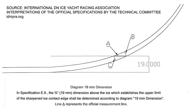
10/1/2010: In Specification E.9., the ¾” (19 mm) dimension above the ice which establishes the upper limit of the sharpened ice contact edge shall be determined according to the diagram “19 mm Dimension”. Line A represents the official measurement line.
12/01/2012: The interpretation dated 11/14/89 is amended to read as follows: Wood, metal, or carbon stiffeners may be added to wood body runners (as in E.1.e.
for plate runners) as long as the minimum wood body meets the dimensions in E.2.a. and the stiffener is outside the wood body. No wood, metal or carbon stiffener may come between the insert plate and the slot in the wood body. No metal or carbon stiffening is allowed inside the main wood body.
12/01/2012: It is allowed to apply a coating to cover the surface of the steel plate, angle, or T used in a runner. The steel, without the coating, shall comply with the dimensions specified in E.1.a.,b.,c.; E.2.f. and E.2.h.
01/15/2013: In runner specifications and interpretations runner stiffening elements, i.e. “stiffeners”, and runner reinforcement have differing allowed uses, allowed materials, and dimensions.
On plate style runners, stiffening elements are controlled by specifications E.1.; E.1.d., e.,f.; E.4; E.6. and interpretations E. Runners dated 11/14/89, 7/1/92; four interpretations dated 1/15/2010; and I. Fittings dated 1/15/2010.
Stiffening elements and reinforcement of the body of wood body runners are controlled by specifications E.2.a., d., e.; E. 4.; E. 6. and interpretations E. Runners dated 10/17/83; 11/23/87; 7/1/92; 11/30/98; four interpretations dated 1/15/2010; 12/01/2012; and I. Fittings dated 1/15/2010
On wood body runners, allowed material added to the body which is outside the allowed maximum body thickness of 1 1/32 inch (26.1 mm) is considered a runner
stiffener or stiffening element. Allowed material added to the outside of the wood body, or in the slot of insert style runners, that does not exceed the allowed maximum body thickness of1 1/32 inch (26.1 mm) is considered external reinforcement.
05/23/2013: It is not permitted to reduce the thickness of the runner steel below the allowed minimum by rounding, fairing, or tapering except as specified for the leading edge in Specifications E.9 and E.12. Refer to the interpretation E. Runners dated 10/01/2010 and the diagram “19 mm dimension”. The 3/4” (19 mm) dimension does not establish a line extending along the runner parallel to the sharpened ice contact edge below which the thickness of the runner steel is allowed to be less than the specified minimum.
02/17/2014 Runners are not considered ballast and runners of different weights may be used during a regatta, provided each runner complies with the specifications and interpretations under E. Runners.
02/17/2014 The interpretation dated 1977, which reads: “It is legal to change runners from a light set (6lbs) each to a heavy set (17 lbs) each during a regatta and not be in conflict with the change of ballast”, is deleted.
DN
Faster.Transportable.Most Popular.
DN RACING
International DN Ice Yacht Racing Assocation
DN North America
DN Europe